3D Printing Vertical Holes: Why They Print Smaller (Fix It Two Ways)
Vertical holes (axis parallel to bed) come out smaller AND oval — bridging at the top causes sag. Two fixes: add +0.10mm compensation, or switch to a teardrop shape that self-supports.
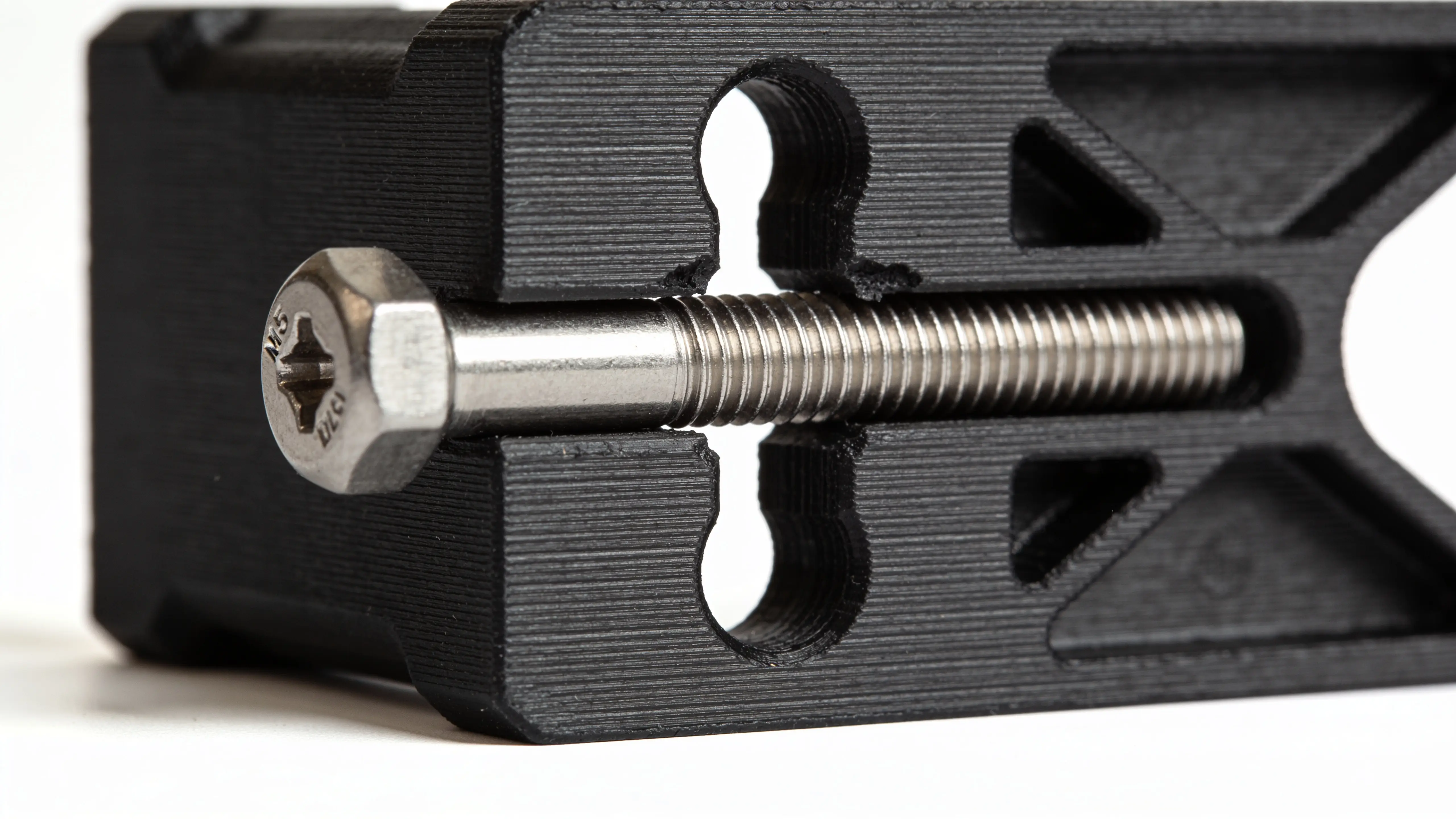
A bolt hole that should be 5mm prints as a 4.7mm oval. The bolt won’t fit, and even if you forced it the threads would chew the plastic. You measure the hole at the top and bottom — top is 4.5mm, bottom is 4.8mm. Welcome to the vertical-hole problem.
Vertical holes (axis parallel to the bed, hole goes left-to-right through the print) have TWO things going against them that horizontal holes don’t:
- Standard hole shrinkage from material and slicer effects
- Plus bridging sag at the top, which makes the top of the hole droop down by 0.1–0.2mm
The result: a vertical hole always prints smaller AND less round than a horizontal one. Bolts don’t fit, bearings won’t press in, the whole assembly fails.
Two fixes work — one adds compensation, the other redesigns the shape. Pick based on whether you can change the model.
Fix 1: Add +0.10mm compensation on top of the normal hole math
Standard hole compensation in PLA on a 0.4mm nozzle is roughly +0.24mm for a 5mm hole (modeling at 5.24mm to print at 5.00mm). For a vertical hole, add another 0.10mm: model at 5.34mm.
| Hole target | Horizontal model Ø | Vertical model Ø |
|---|---|---|
| 3mm | 3.26mm | 3.36mm |
| 5mm | 5.24mm | 5.34mm |
| 8mm | 8.20mm | 8.30mm |
| 10mm | 10.18mm | 10.28mm |
| 15mm | 15.12mm | 15.22mm |
| 20mm | 20.08mm | 20.18mm |
The Hole Tolerance Calculator handles this automatically — pick “vertical” orientation and it adds the +0.10mm sag compensation to the formula.
Why it’s not always enough: the top of a vertical hole isn’t just smaller, it’s oval. The sag pulls the top edge down but leaves the bottom round. A bolt going in catches on the deformed top edge even if the diameter is correct on average. For tight fits (bearings, dowel pins) you also want the second fix.
Fix 2: Redesign as a teardrop shape (this is the real answer)
A teardrop hole has a 45° peak at the top instead of a flat top. The print bridges across the peak in a way that’s self-supporting — no sag, no oval, no compensation needed beyond standard horizontal math.
Standard circular vertical hole:    Teardrop vertical hole:
  ╭─────╮                              ▲
 ╱       ╲                            ╱ ╲
│    ●    │  ← top sags             │ ● │
 ╲       ╱                            ╲ ╱
  ╰─────╯                              ╰─╯
                                     ↑ self-supporting peak
Most CAD tools have a “teardrop” or “self-supporting” hole option:
- Fusion 360: Sketch a circle + add a triangular peak at top
- Onshape: “Hole” tool → “Counterbore + teardrop” option
- OpenSCAD: Boolean union of cylinder and a triangular prism above it
- FreeCAD: Sketch a circle, then a triangle on top, pad both
- SolidWorks: Custom feature — combine a cylinder with a 45° wedge
The peak angle should be ≤ 45° from horizontal for clean printing without supports. A 30° peak prints even cleaner but takes more vertical space.
Functional impact: the teardrop shape has a slightly different cross-section at the top (a small “ear” of plastic), but it doesn’t affect bolts going through — they pass through the round portion below the peak. Bearings sit in the round portion. The extra peak material is purely cosmetic / structural.
When to use which fix
| Situation | Fix |
|---|---|
| You can’t modify the model (downloaded STL) | Add +0.10mm compensation (Fix 1) |
| You’re designing in CAD and can change the geometry | Teardrop (Fix 2) — strictly better |
| Holes are decorative (no bolts going through) | Either |
| Holes need to fit a precise bolt or bearing | Teardrop (Fix 2) |
| Multiple stacked vertical holes (heat sink, ventilation) | Teardrop on all of them |
Teardrop is the engineering-grade answer. Compensation is the workaround when you can’t redesign.
Why does this even happen?
When the 3D printer reaches the top of a vertical hole, the slicer has to bridge across unsupported space. The molten plastic spans the gap, but it sags downward as it crosses — gravity pulls it before it solidifies.
The physics:
- Bridging works for short distances (≤ 5mm) and produces clean undersides
- Bridging over 5mm starts to sag visibly
- A vertical hole’s top is essentially a tiny bridge — the diameter of the hole is the bridge length
- Larger holes sag more proportionally
This is why teardrops work: a peak gives the printer something to land on layer-by-layer, no bridging required. The plastic deposits onto the peak’s slopes and self-supports as the peak narrows.
Other approaches that mostly don’t work
Print support inside the hole. Slicers will offer to add support material inside the hole. Don’t. The support is hard to remove, leaves a rough surface, and the hole comes out fuzzy or out-of-round.
Slower print speed at the top of the hole. Helps slightly (~30% reduction in sag) but doesn’t eliminate it. Compensation is still needed.
Lower layer height. A 0.10mm layer height vs 0.20mm reduces sag by about 30%. Worth it if you’re already doing detailed work, not worth the print-time penalty otherwise.
Variable layer height around holes. Some slicers (PrusaSlicer, OrcaSlicer) can vary layer height per region. Useful for production parts where you can’t redesign and need maximum accuracy — set 0.08mm layers for 2mm above and below each vertical hole.
Hexagonal vertical holes (you’ve seen them in some Voron parts). Hexagons are 6-sided polygons — they print cleanly because there’s no bridging, just 6 straight edges. Useful when the function allows a non-circular hole (heat-set inserts can fit hex pockets). Doesn’t work for round bolts/bearings.
The two-line summary
- Vertical hole, can’t change the model → add +0.10mm beyond horizontal-hole compensation
- Vertical hole, you design the CAD → use a teardrop shape (45° peak), then use standard horizontal-hole compensation
For everything else about hole tolerance — material differences, polygon-approximation effects, calibration to your specific printer — see 3D Printed Holes Too Small? Exact mm Compensation by Material. The full calculator with vertical-orientation toggle is at Hole Tolerance Calculator.